Thursday, June 12, 2014

Stuff...

Ok, haven't gotten much build work done, since I realized I was in need of a couple of things.

First off, I spent a good 3 days reading posts both at k9.replicarobots.net and at whoprops.proboards.com about what everyone else was using for their lights on the control panel.

Most everything I found was going to be in the neighborhood of $120 to $150 after buying all the parts.

I spent several hours just plain googling terms trying to find something better, and came across an EBay link that looked promising, at least for info on some part numbers.  Turns out, what I found (if it's what was advertised) was almost exactly what's needed. 

Here's some links for reference:

Clear indicators
 
Green indicators
 
Blue indicators
 
These are the same 18x24mm size as I see a lot of people using.  I know the SunMulon are 14.2x20.2, but for $120 I think I can live with those extra 3.8mm each way.

I'm going to go with the 2006 Hero panel layout, and the total price including FREE SHIPPING  was a whopping $28.23! 

Much less exciting, but I also picked up my neck surround/gaiter/whatever you want to call it.  Found a link with pic in someone else's build thread for Blo-R-Vac Duct Hose, got a whole foot for $5.28!  The pic I saw looked like it should be the right stuff, and I didn't have to buy 20' of it.  It's not cloth, but I think it's going to look ok since it will probably match the tail boot (once I get one...)

***Edit***
Oops...I just checked my links and it looks like at least on the red ones, I got the last ones.  Maybe they'll add some more.


Tuesday, June 3, 2014

The Head begins


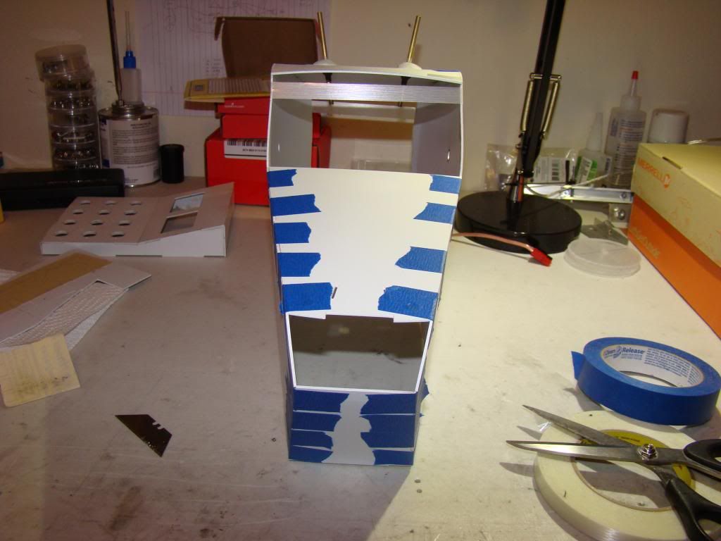
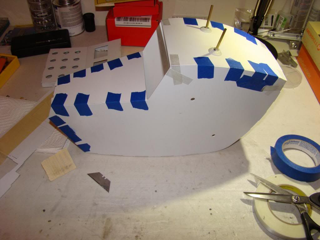
Began assembling the (some say) giant head last night.

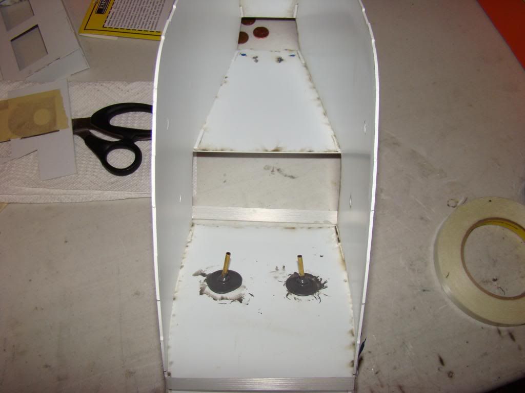
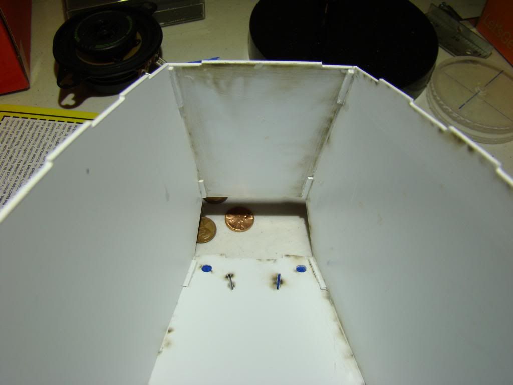
Here's some pics of the top, sides and nose part taped together:


When I glued the pieces, I also used some scrap pieces to reinforce the corners:


Annnnnnd, that's all for now.  Phew.  Only took 2.5 hours to write these last 5 posts.

Working on code is next.  It all works, but using 'delay()' in the code, which is a bad thing.  Apparently when the Arduino hits delay, it stops and waits until the delay is done before accepting or processing the next command.   That means if I'm driving and tell K9 to wag his tail, either he keeps driving while doing so, or he stops to wag his tail and won't move or speak until he's done wagging. I don't know which, but you can see how it'd be a bad thing.

I'm working on figuring out how to use 'millis()' in the code, which measures the Arduino's clock cycles and then uses comparisons to when things happen to determine how long to wait.  Since it's a comparison it only takes a fraction of a second ands doesn't disrupt other operations.

I'll post more when there's more to be posted!


Mobility!

This one's about the base again.

I may have mentioned earlier that I was going to have to stiffen the base, since it had so much flex.

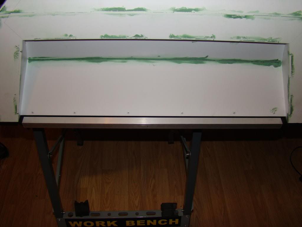
 I was trying to decide how and where to mount the aluminum U-channel that was left from the neck, when I realized what it's actually for.  It's for cladding the sides of plywood sheeting.  Problem solved!


And, luck struck once more, since the pieces are just the right size:


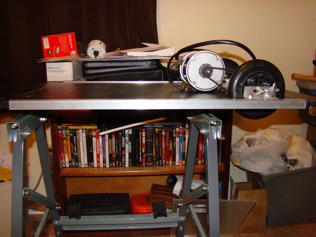
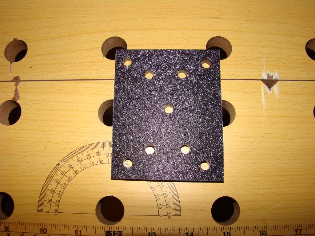
Next job was mounting the 2" casters in the rear.  Start off with a bunch of holes in a small piece of plastic:


Then mount the casters to the plastic piece and drilled the 2 3/4" holes:


And then, there's not a good shot of the casters bolted to the base.  *shrug*

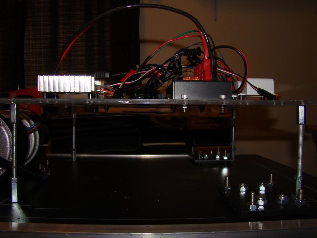
Next I mounted the electronics board to the base:


When I put the body on, the electronics board was too high, the inset panels of the body hit the board, so I had to lower it by 3/4".


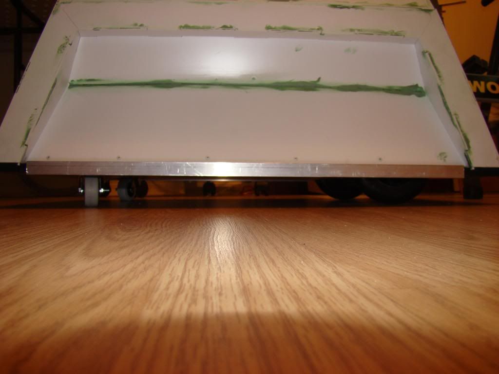
Here's a shot of the clearance when the whole thing is put together and on the floor:


Next up:  The giant head begins!


Electronics!


As mentioned, up next is electronics, always a highlight!

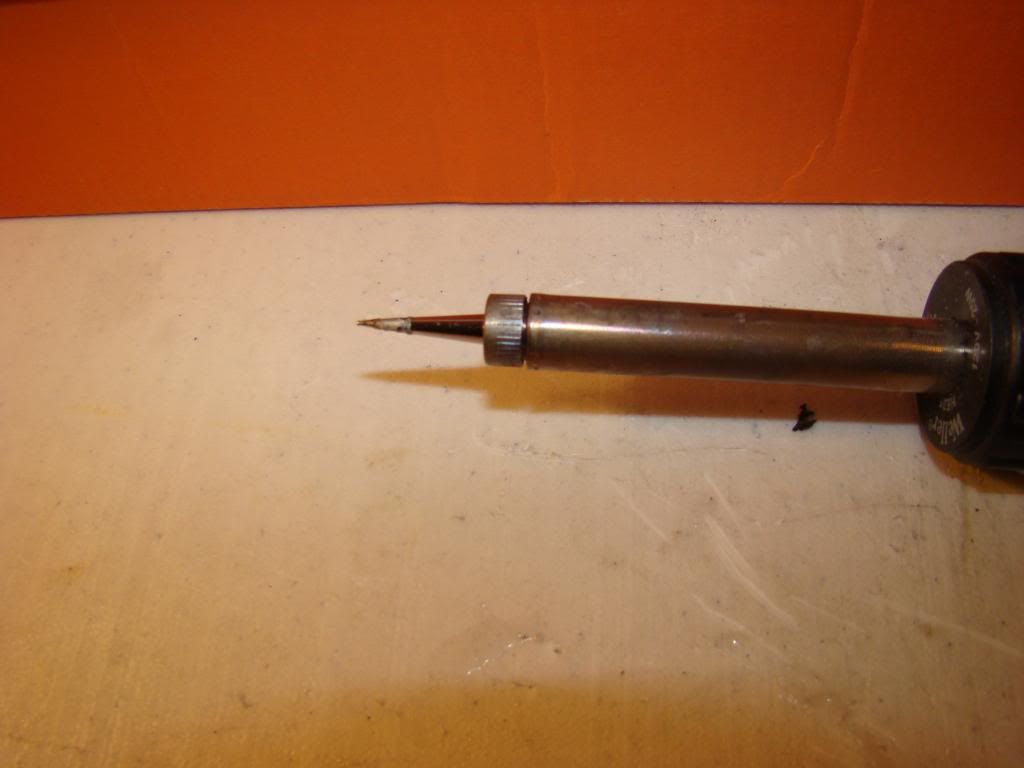
I've never been very good at soldering.  I thought maybe a new tip for the soldering iron would help, and boy did it ever.  Originally had a "screwdriver" tip, so I ordered the pointiest tip I could find.

Here's a pic, just for fun:


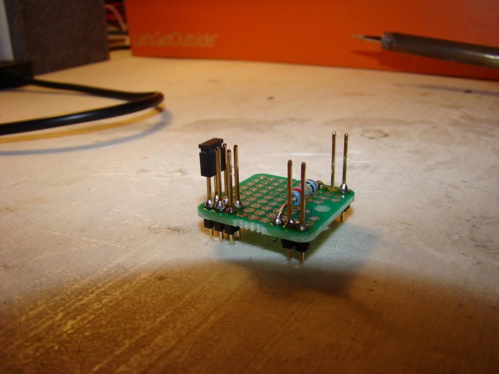
Here's a pic of one of my small boards:


This one adds the 10k resistor between the wireless receiver's power (red) and data (brown) lines, and since there was plenty of extra space, I made a spot for common grounding of the components.

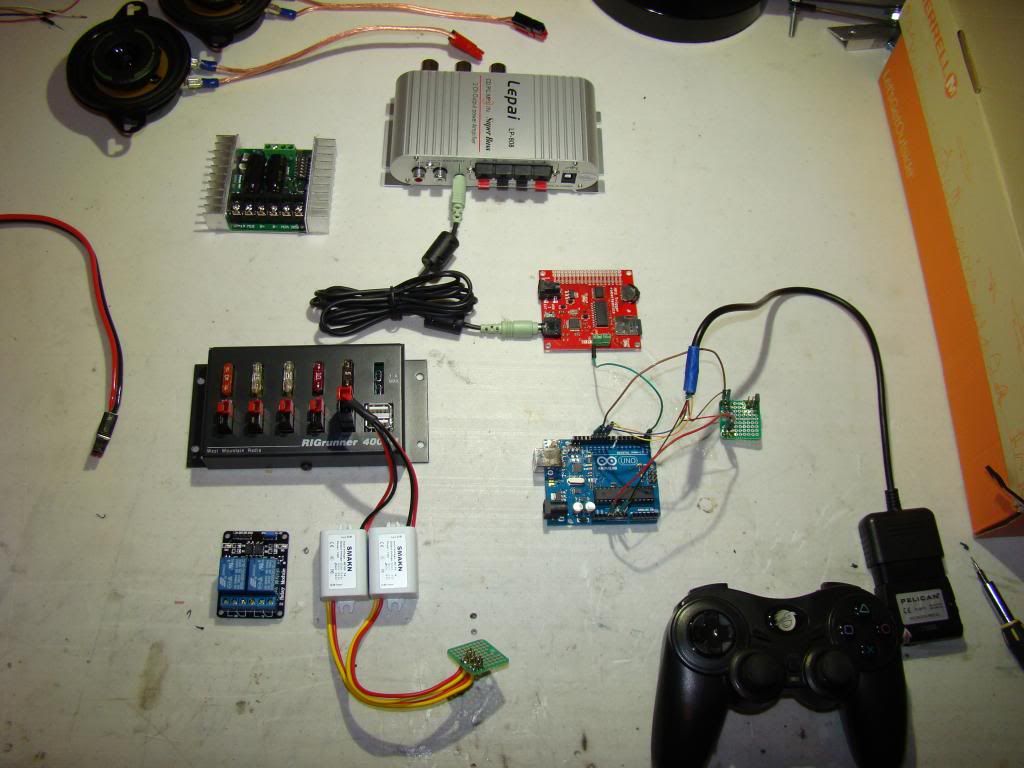
Here's a pic of everything laid out in what'll wind up being the final layout:


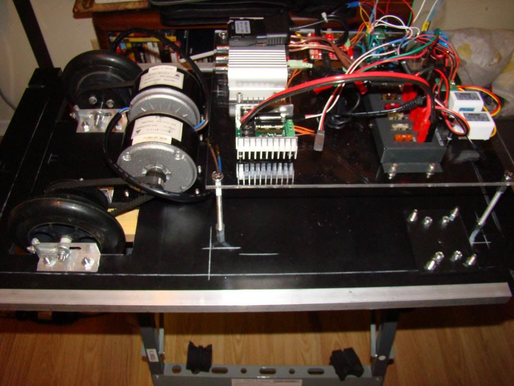
From top to bottom, there's the speakers, the silver audio amp, the green SaberTooth 2x25 speed controller, the red MP3 Trigger, the RIGRunner fuse block, the blue Arduino Uno, the small green board I showed in the previous picture, the white 12v-6v DC-DC converters, the blue dual-channel relays, and another small green board I made, that's for splitting out the power from the DC-DC converters.  Phew, that was a mouthful.

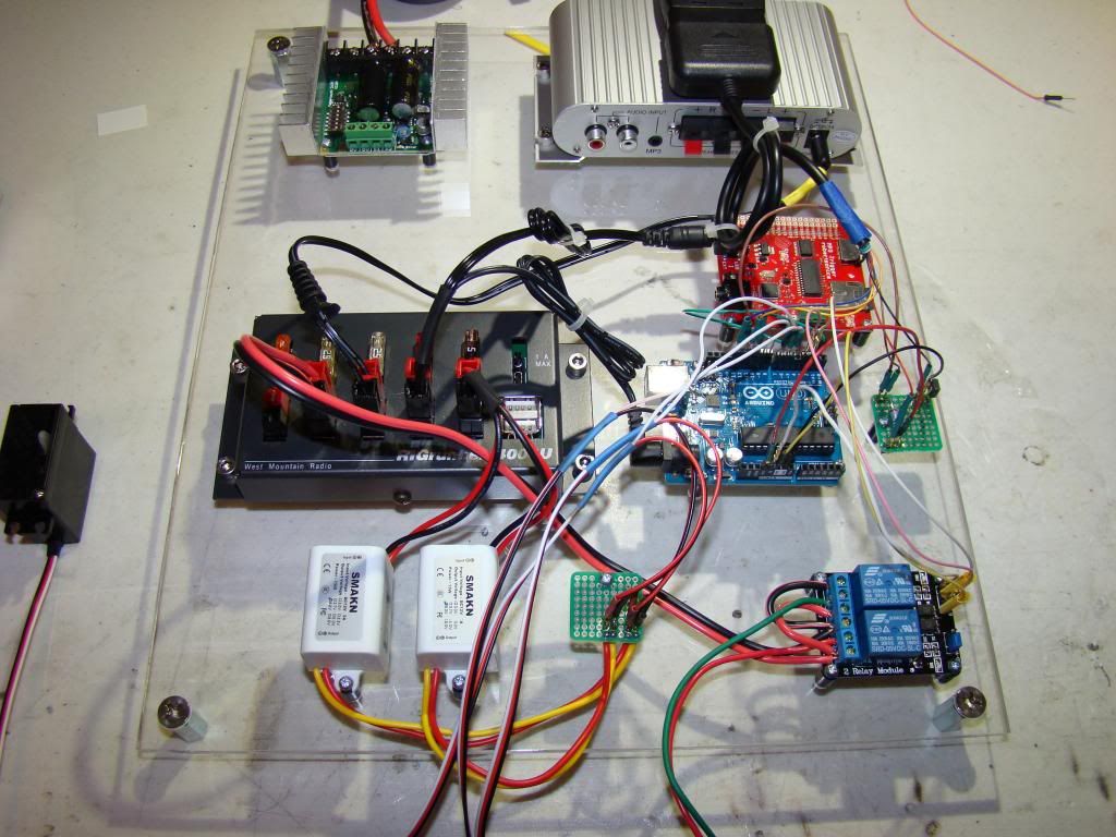
Here's a shot of all of that stuff with more wires connected :


And a shot of everything mounted on the board:


You can see that the SaberTooth isn't connected yet, that'll come along later.


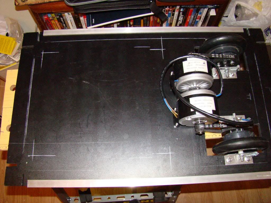
Drive train

I could have sworn I took a couple dozen pictures of building the wheels, but all I can find is:


There are no pictures missing according to the numbering scheme.  Oh well. 

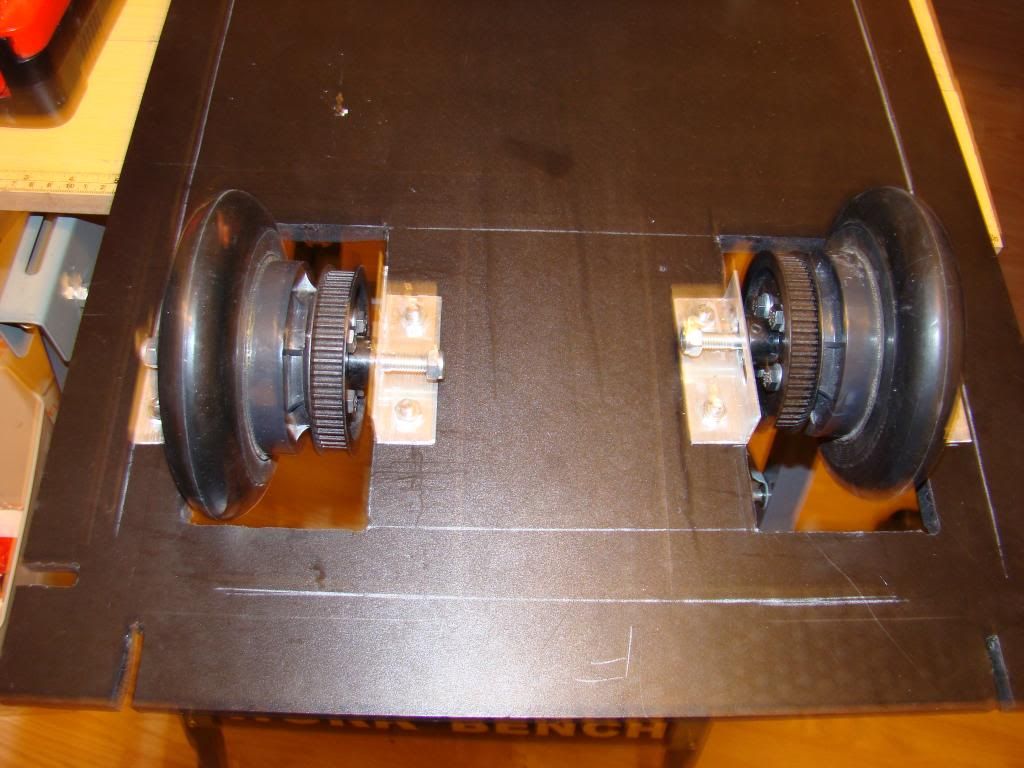
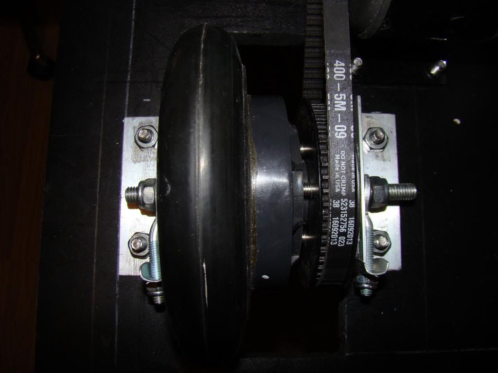
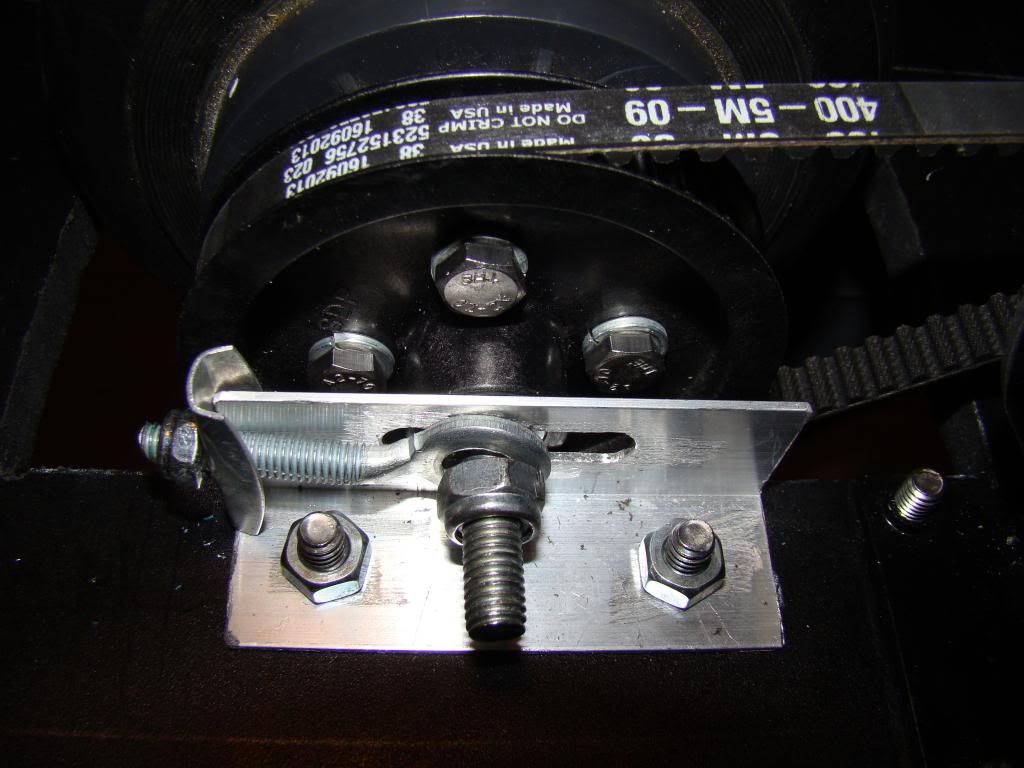
What I did was remove the chain cogs from the wheels, and replaced them with these cogs from Amazon.  I did have to drill them in order to mount them, but luckily I had the cogs as a pattern.  I did have to buy longer bolts, but that was easy enough.

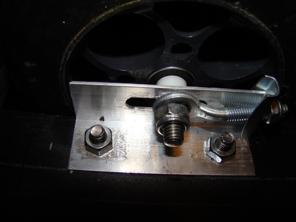
I also cut some aluminum angle, drilled mounting holes on one side, and adjustment slots on the other side.  I used the axles that came with the wheels since they were pretty close to the correct length, and I even managed to use the adjustment washer-bolt thingies.


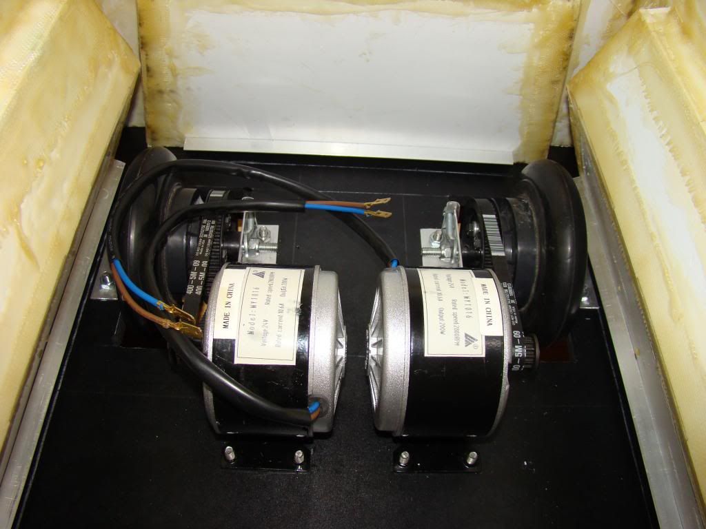
Here's the whole drive train assembled, and some close ups of the wheel assemblies:


Here's an inside shot of the base and the body assembled. Had enough clearance the first time around, didn't need any adjustments, can you imagine that??


Here's what it looks like from the underside:


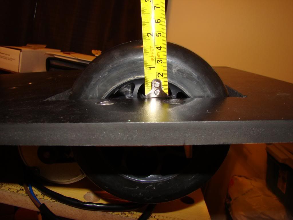
And a shot measuring the clearance, which SHOULD be plenty, since R2 only has about an inch between his footshells and the ground:


Next up:  Electronics!


Lots of updates...start with the base

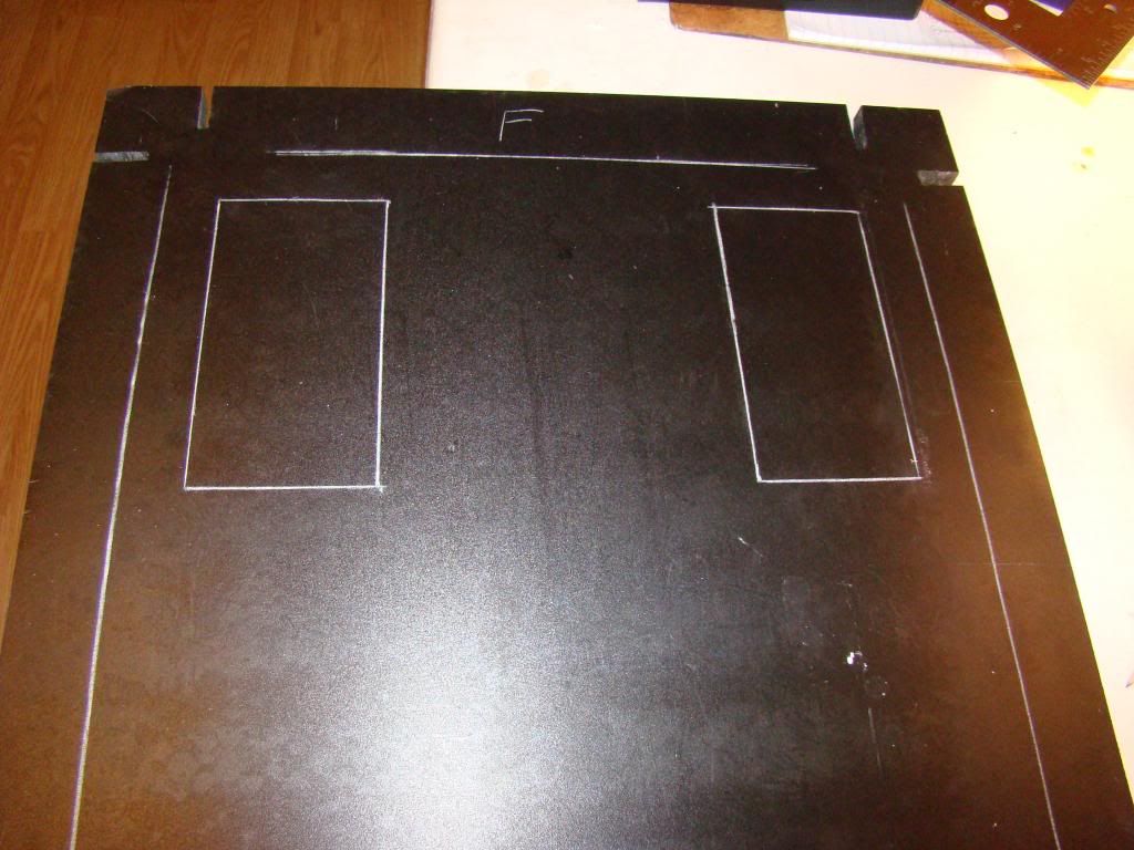
So, I've been busy and haven't had time to post any updates. Got a spare evening tonight, so I thought I'd catch you guys up. We'll start off with frame work. I had to notch the base plate so the body would fit:


Next up, laying out and cutting out the holes for the wheels:


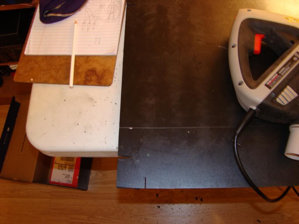
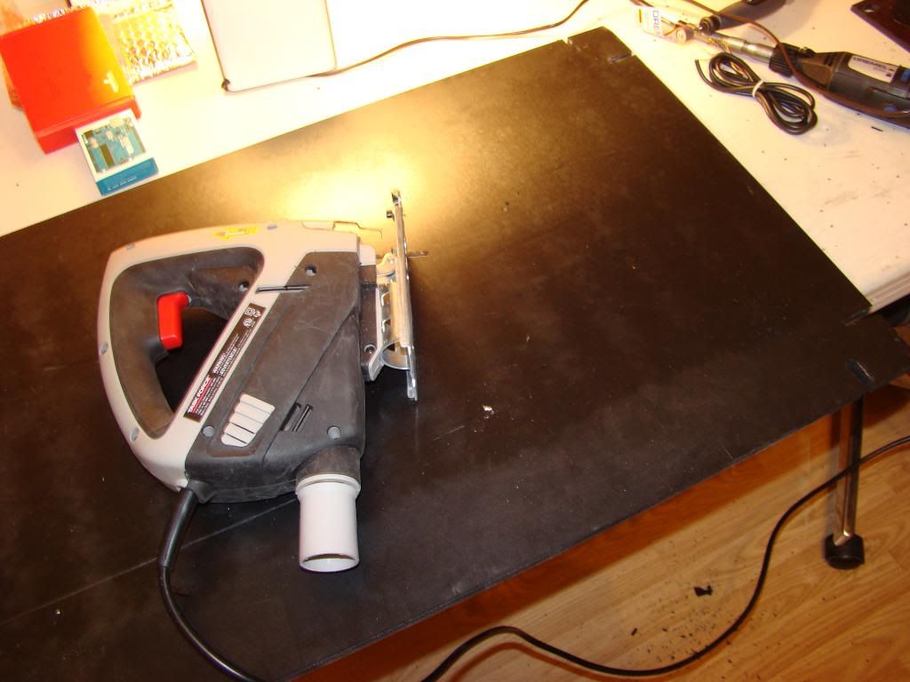
Now you'd think that with a straight edge, I'd be able to cut a straight line.  Not the case.  Apparently I own the crappiest jigsaw made.  On the first two short cuts, the saw ran true, but the blade moved almost half an inch out of line.  I wound up doing a much better job free-handing the remaining cuts:


I'll cut this into several smaller posts to make it easier to search for stuff later :)


Sunday, May 11, 2014

Friends, Romans, Countrymen....

So, this post is mostly about ears work.

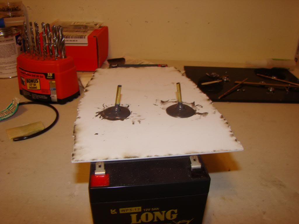
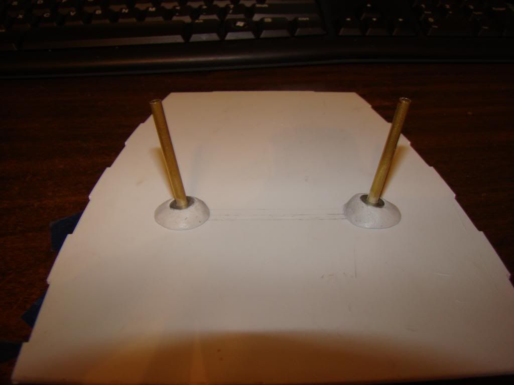
We start off with a picture of the jig I made to hold the tubes in place:


It holds the tubes pretty close to 10 degrees off center.  Credit for this idea, as well as several others goes to fellow K9 and astromech builder Doug Dixon.

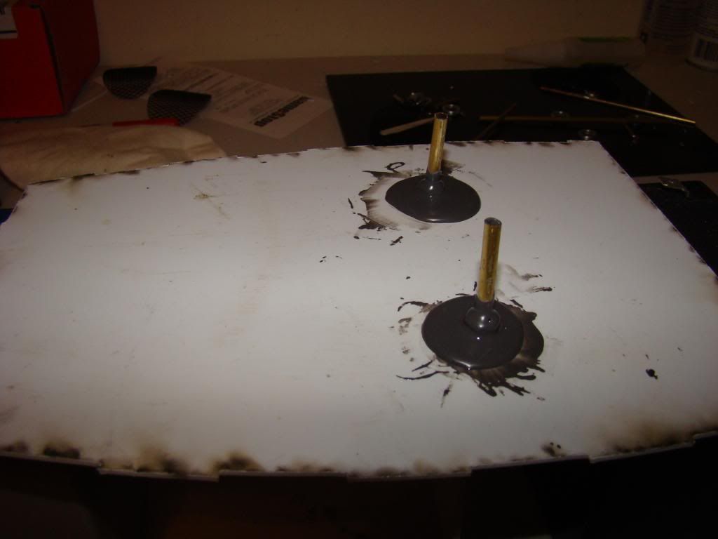
On the bottom I used a washer and a nut that just happened to fit fairly well on the tube, and I JB Welded it in place.  I'd forgotten how messy that stuff can be, and how even after 2 or 3 hours it will still run, albeit very slowly:


for the top of the head I considered coming up with some sort of mold to hold the JB Weld in place, to keep it from settling, but decided against that.
What I ended up getting instead was JB Weld's PlasticWeld, an epoxy putty.  I'd intended to get the SteelStick, but had a brain fart and grabbed the first thing that sounded right.  Guess it's a good thing the head is made of plastic...

Anyway, the stuff looks like what the 'As Seen On TV' guys were selling a few years ago, one color outside and another color in the center.  You just start kneading it until it's all the same color, then you have 20-25 minutes to get it how you want it. It's kind of like thick Play-Doh.

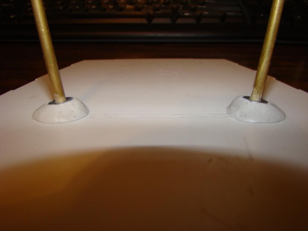
Here's what I did with it:


It's supposed to be cured in 2-3 hours and be sandable and paintable.  We'll see.  The washer on top of the putty is for the pen tip to ride on, once that stuff is all built.

Now that this part is finished, I'll be able to go ahead with assembling the head.

Tuesday, May 6, 2014

The "ISSUE"...

I almost forgot.  I mentioned "There IS a little issue, well actually a huge issue, but I don't have any pics, so I'll just have to leave you hanging whilst I figure out exactly what to do about it."

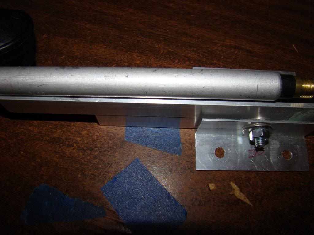
So here's a couple of pictures of the problem...


The U-channel is apparently thicker than what the plans call for.  The antenna mast doesn't fit inside of it. 

Right now the plan is to mount the antenna exactly like it shows in the picture. 
In order for the antenna to come out of the head where it's supposed to, I'm going to have to change the angle at which the head mounts to the neck, but I think I'd have done that anyway.

We'll see how it plays out I guess.  The beauty here is that I don't think anything I do can ruin a part that can't be remade in a few minutes.


Sanding

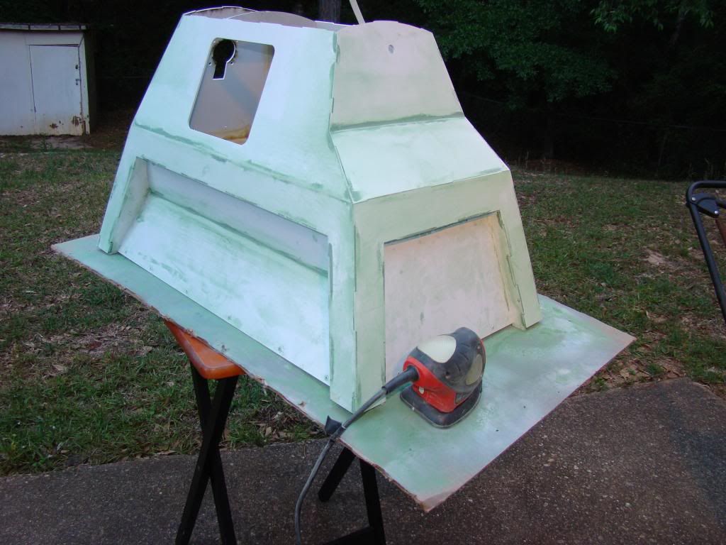
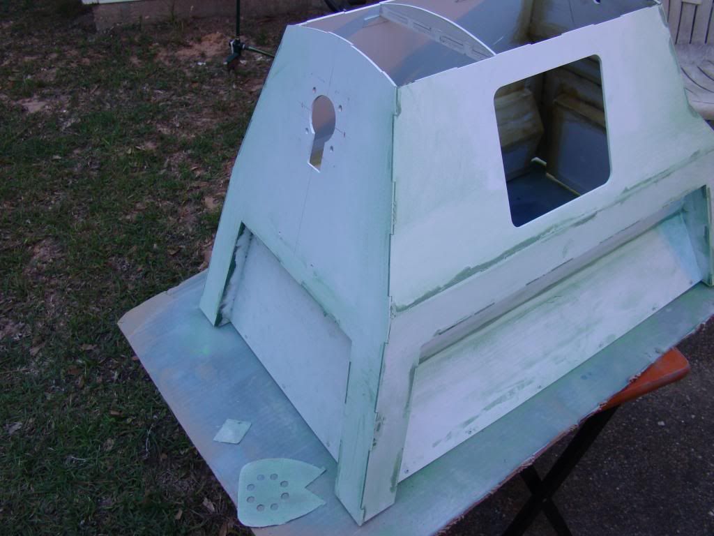
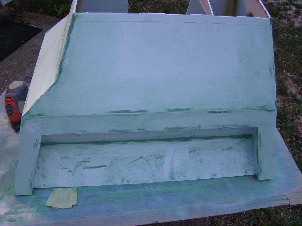
Well, as promised here are a couple of post-sanding round one pics.  Maybe they'll be "good enough" and won't require a 2nd application.
Turns out that with my mouse sander, the Squadron Green modeling putty sands pretty easy.  I am glad I took it outside, there was a lot of green dust.


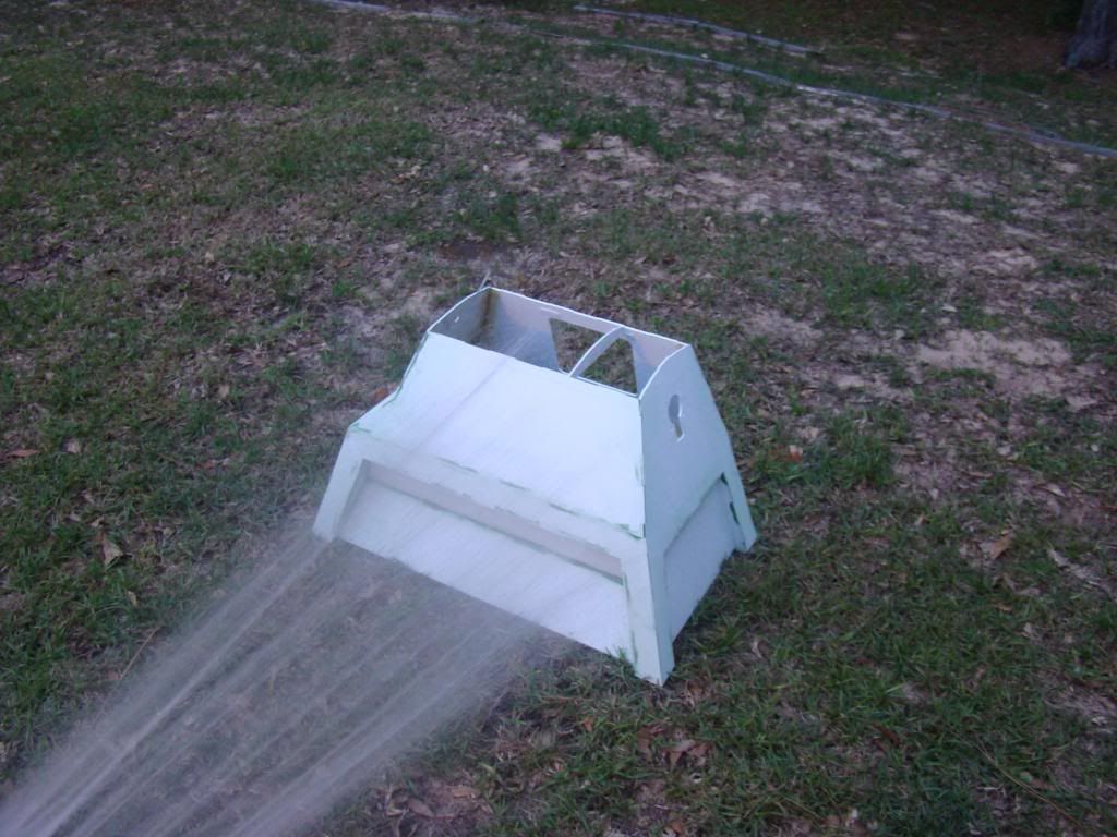
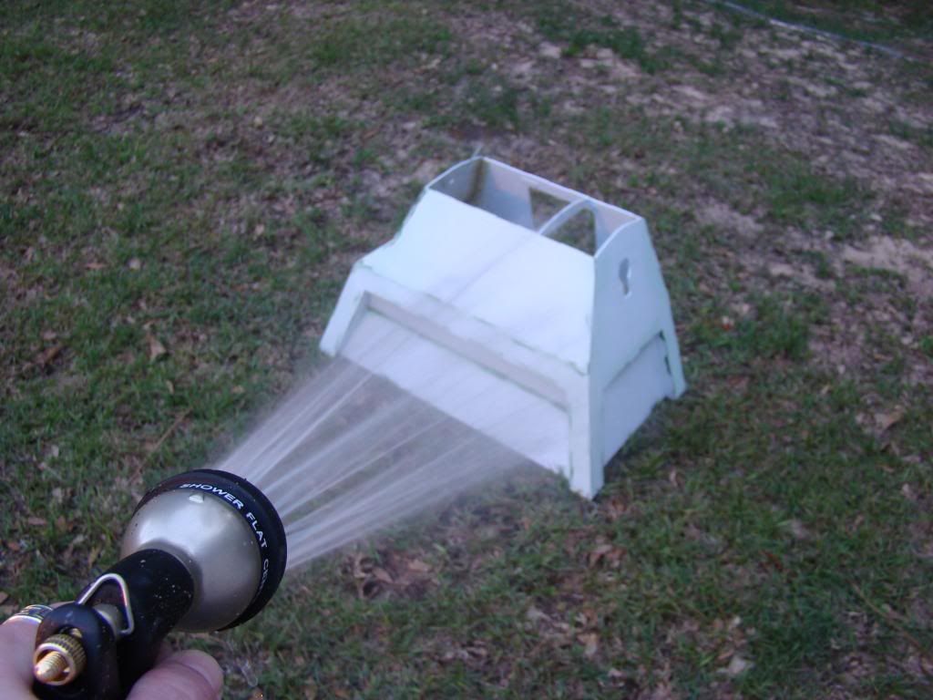
And here's a couple of pics of K9's first (and hopefully only) bath...


Seemed like the easiest way to get all the green dust off of him.  I didn't want to risk putting him in the shower and wind up with a green tub :)

After, I was trying to decide which towel to risk for drying him off, then that little voice in the back of my head said "Duh...use the GREEN towel ya Mo-Ron".

Tomorrow I'll shoot a little primer on the seams and see how they look.