Sunday, December 28, 2008

Update

Not a lot going on due to the holidays. I have been getting stuff in the mail though. Seems like every day I have to spend my lunch break driving out to the airport branch of the post office.

Anyway, enough complaining.


Here's a couple of pics of the "Beefy Ankles" from Resin Parts.com and how they attach.

I just did what I saw Kelly Krider did.


The screws are both drilled by hand at an angle, and countersunk. The ones on top of the ankle didn't work out 100%, so I just took the dremel to the edge that was sticking up.


Here's pics of the parts that have come in so far:

Razor E100 wheels, chains and motors.


The dome motor mount assembly and wheel from Atomic Pickle


This week I'll be getting in the speed controllers for both the foot motors and the dome motor, as well as the dome motor and the power dist board from PowerWerx.

I've almost figured out making the motor holders, just got to get the material and the template. Gonna follow the Dan Baker Method for that.

Thursday, December 11, 2008

RC explanation (sort of)

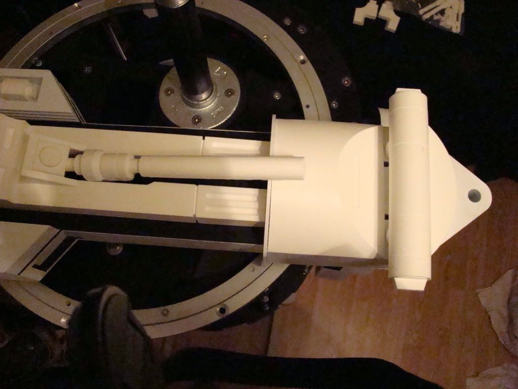
Ok, as promised, going to try to explain the whole RC thing. At least the dome motor and drive motors part.

As a note before I start, the hardware I'll describe is pretty close to what I plan on using. Other stuff might be different...

We'll start with the transmitter. Mine's going to be the Futaba 6EX. That seems to be the most popular one.

The drive motors will be controlled by the left joystick, using what's called "mixed mode". I don't know exactly how it works, but Droidwelder gives a description here. The means that both motors will be controlled by one joystick, using channels 1 and 2.

The right joystick will be for spinning the dome one way or the other using the side to side (probably channel 4).

So, when you use the joystick on the transmitter, it sends the signal to the receiver, which will look a lot like this:

Receiver

When people refer to "channel 1" or "channel 3", those correlate directly to the numbered plug holes on the receiver. So far, our signal has gone from the joystick, out the antenna, to the receiver and to the 3 wire plug hole you see above. They are also sometimes keyed, so you can't plug them in backwards, which would make the motor run backwards.

Next up is the speed controller. A speed controller is exactly like a dimmer switch for a light bulb. News to me, instead of limiting the power like I thought it would have, it switches the power on and off really fast. How fast depends on the position of the switch (in this case the signal). So apparently a dimmer switch turns the light on and off so fast that the filament doesn't have time to warm up completely. Supposedly from an electronics standpoint this is far more desirable, because it produces less heat and stuff. I'll take "their" word for it... It also produces that hum you might hear from a dimmed light sometimes.

The Scorpion XL speed controller looks like this:
Scorpion XL speed controller

Looking at this picture is where everything kinda clicked for me...You can see the 3 sets of 3 wires with the little plugs. Those go to the receiver. Offhand I'd have to guess that the one labeled "right" goes to the channel 1 output, the one labeled "left" goes to the channel 2 output.

And now for a quick break to explain what I think the one labeled "comm" does. On the bottom left side of the board, you'll see something labeled "BEC". This is the connection for the "Battery Elimination Circuit". What this does is provide 5v of power, so that you don't need a power source for your receiver. My only slightly more than un-informed guess is that the set of wires labeled "COMM" will plug into the port for output 8, which is labeled in red in the first picture, thus eliminating the need for a battery for the receiver.

By now things are probably starting to click. The motors will attach to the appropriate screw-down block. The power from your battery (Or power distribution board/fuse block) will attach to the top set of screw-downs. BTW "screw-downs" probably isn't the correct terminology for those parts, it's just what comes to mind without having to research what it really is.

The dome motor will work almost exactly the same, but it will have it's own speed controller, and will use channel 3 or 4, depending on how the transmitter is set up.
I was also told that under no circumstances should you use the BEC from both power boards. One will suffice.

Ok, so that's what I know about RC so far. You'll notice there's an awful lot of "I think" and "probably" going on in there...if I'm not right about something, please don't hesitate to speak up. Better to have to edit a post than replace a part that blew up because I connected it wrong. But that should be enough to clear up a little bit of the mud.

It sure does sound a lot like red wire black wire, doesn't it? Plug it into the right place and it goes...plug it in wrong and it either doesn't go, or it goes backwards :P

Oh, before I forget, a big thank you to Droidwelder over at astromech.net for answering questions for probably the umpteen thousandth time...

Monday, December 8, 2008

Got my shipment in from Resin Parts.com!

Can't believe how cool they are...and how much more work I now have to do...

Here's pics:

Spread out on the bed (not all of them, just the ones that aren't in the next pictures):


Leg parts laid out, as close to in place as I could get them just eyeballing:


Yup, as I said, way more work now to do. And I am digging the "beefy ankles"...they are very cool. I made sure to read the
Working with resin page and I dont' have anything to clean the mold release off the parts with yet, so I'm just letting them sit.

Mainly doing more research this evening...I think I've just about got the RC bit figured out. Once I'm sure I know what I'm talking about I'll tell you what I figured out. :)

Tuesday, December 2, 2008

Ok, so you can't really tell in these pics that all the gaps are filled, but here they are anyway...


Monday, December 1, 2008

Oh, as a side note to the previous post, I think I figured something out about the "LPJT".

I'm having trouble getting a single pipe that will fit between the 2 galvanized floor flanges.

Apparently when you thread a pipe, the threads are tapered. Not so much that you'd notice, unless you were trying to thread a flange that quite also might possibly have tapered threads as well onto it.

Basically, my measurement was 14 1/16" between the flanges. I had the very stressed little man at Lowe's leave 14" between the threads when he made the pipe for me. Since I can't thread the flange all the way to the end of the pipe, that just plain doesn't work.

I plan on going to Ace Hardware (Since it's usually old dudes who like a challenge and seeing if they can fix it. My money says yes, although I might have to buy a 3/4" tap and die that I'd never use again....

Anyway, that was important enough to mention since I spent 7 hours Friday working on it. Maybe THIS is why 2 pipes is the common method...

Update

Ok, no pics this time.

Now that I know someone's reading this,

Big shout out to Greedo who makes the best clone carbine you can get your hands on (if you're lucky) :)

The legs are done being skinned with sintra, but there was a mishap...one of the legs fell and the "ankle bracelet" broke. Will have to stupid glue that back on.

Also noticed a slightly bigger problem, but not one that normal folks will see. My horseshoes are identical. Meaning when sitting side by side they look the same and are not mirror images. Means I'll have buttons front on one side, and hydro front on the other. John Q will never notice, and possibly only people who read this will know to look :)

Anyway, got that big box o' parts ordered from Keith at resinparts.com (link in the previous post) and had an email today that it shipped! That kind of motivated me to find something to do.

2 weeks ago I ordered an 8oz bottle of CA glue from the local HobbyTown USA. When I picked it up Black Friday, you'd have thought I was a celebrity or something, because everyone working there wanted to see who ordered it and what I was working on to need that much glue.

Basically, I refuse to use Bondo ever again, and am using CA glue and accelerant as a filler, and then sanding that down. It's working really well so far, except that I didn't anticipate the mess I made sanding, and I'm fairly sure my computers are all now white inside.

Anyway, took about 3 hours (I guess) to do the middle foot tonight. It still needs about 2 minutes of sanding on the top of the foot, just plain didn't get to it tonight, because HEROES, the best show ever, was on. Had to stop sanding so I could watch :D

Also had to buy new accelerant, since the last 2 bottles were empty, and this kind isn't as fast as the last 2, although it could be the cold weather making it take a little longer to "kick".

Well, as soon as I feel I need pics, I'll post 'em.

Thanks for reading :)

Saturday, November 22, 2008

No pics today...still working on "skinning" the legs with sintra. All that's left is the strip over the top of one leg. Takes a lot of CA glue to get that done.

What is new, is I did send a large order to
Resin Parts.com. not sure when it'll come in, but it's all kinds of stuff. Mostly parts for the legs. I'm looking most forward to the "Beefy Ankles" that they sell.

I guess the main reason I keep putting off the last little bit of leg stuff is that all I will have left after that will be the skins for the frame. I know once I start it'll be nothing, like the rest of it has been, but anyway....

Monday, November 17, 2008

Leg Pipe Joining Thingy

A guy named zorg made a post on Astromech.net and called this the "Leg Pipe Joining Thingy", but I'll shorten it to LPJT. :)

In order for this post to make any sense about how the LPJT will work, you might need to read the previous post first, to see how my shoulders work. I'll wait while you do that :)

Well, right now my plan is to have 1 pipe (3/4") between the shoulders, instead of trying to find the 1" pipe and the 3/4" pipe to fit inside it.

Here's what I have so far:

I took the inside circles that already had T-nuts (which hold the legs onto the body) and added new holes for another set of T-nuts, like so:


The new set of T-nuts will come from the other side. In order for the leg to still rotate smoothly when the bolts are loosened, I had to countersink the new T-nuts with a handy-dandy new 3/4" Forstner bit:


The trick is that now that the T-nuts are facing opposite directions, the legs will bolt into one side, and the flange is bolted onto the other side, facing into the frame. Here's a front and back shot:


If I find out why 1 pipe doesn't work for everyone else (the hard way, I guess) I should be able to swap out one of the flanges and change it to the 2 pipe type. I do still have 2 more of the round thingies in case I really messed this up or something...

The pipe i plan on buying is 18" long. Right now my best calculation is that I won't need to have the pipe cut, just threaded another 2 inches or so on both ends. It might be good, depends on the hubs, once I get some.

I guess the idea is that I won't ever have to remove the pipe, or the discs it's attached to either. After pondering the 2 pipe idea, all I can figure is that the pipe is attached to the legs and must have to come apart to remove the legs.

I guess the real test will be how much stress is passed to the pipe with my setup...

***Important Note: The bolts you saw sticking out of the new T-nuts in the last picture will have to be cut down about 1/4". Since you can see them sticking out, there's no way they will move smoothly when the shoulder needs to be rotated***

Thursday, November 13, 2008

A&A Shoulders

Ok, I said I'd post shoulder pics next, so here they are. I spent a lot of time with the measuring tape and took a leap of faith that one of the parts, mainly the T-nuts would work.


You can see they did :) I used a 5/8" OD 1/2" ID x 1" spacer and the bolts and washers to pull the T-Nuts into the extra pieces, which I'm pretty sure are from the satellite motor shoulders, which I'm not using.

Next up:
Photobucket

All the pieces stacked together for a test fit. I used the unused pieces from the JAG stops to test with, since they had the correct thickness. You can also see I chose to use all of the shoulder spacers. I THINK there's room to remove one when I'm way closer to done if needed.

I used this piece of the JAG stuff for the actual shoulder, because the slots are 1/4" like the rest of the holes. Didn't want stuff to be all wiggly (and stuff :P).

Photobucket

Here's what it looks like all bolted together:
Photobucket

I used 8x 1/4-20 x 2" stainless hex cap screws (They were only like 17 cents more than the cheap ones), 8x 1/4" hardened flat washers (because hardend sounded like it was better than the plain ones) and 8x T-Nuts Pronged 1/4-20 x 7/16".

The spacer rings were countersunk and screwed to the leg with the 10 x 1 1/2" screws that were left over from the frame build.

That's all the hardware.

Here's the leftover plastic pieces. The smaller round piece with the holes (not slots) is what's used as the inside piece of the shoulder (the thing the T-nuts are in).

Photobucket

Here's the fun pictures, where the parts start to come together and even this far from finished you can tell what it is...

Photobucket

Photobucket

And since one of the feet was kind enough to be tight enough to stay on without a pin or something, some even better shots:

Photobucket

AND:

Photobucket

that's right folks, the shoulders are adjustable. Since I used the JAG stops, all it takes is about 1/2 turn with a ratchet on each bolt to have it freed up enough to move to the other position.

Oh, and if anyone is reading this and you should want to see more pics of this, better let me know while R2 is still this naked...

LEGS!

Here's pics of the completed legs. I'm not sure if the pics are of one leg or both. Doesn't REALLY matter, now does it?


Since I mentioned it in a previous post, I'll tell what I did.
I used PVC Cement, Oatey's, to be specific. I glued the inside layer and the piece with the channel together first, then let the cement set for about 15 minutes. Then every 10-15 minutes I added another layer until the 5 main layers were done. Naturally clamps all over the place.

I let them set overnight (Yes, set, I'm talking about the glue, not the legs...I'd have said "I let them sit overnight"...).

That day I also built the ankles, using CA glue and clamps too.

On the 2nd day I added the 2 outside layers, which include the part that fits into the ankle. I also added the bracelet and the backside of the ankle.
A little more CA glue, and I screwed the ankle in place using the 6 little holes at the bottom of the legs.

Rinse and repeat...

They still need to be "skinned" with the Sintra and have that little line cut around them.

Next post: SHOULDERS! (they are done but I don't have time to post the pics right now...
More pictures...Magic Laigs! Jes' like Lootennit Dan!


I've got more pictures, just haven't uploaded them yet


Now look what happens when I don't post for a few days....and what also happens when I don't post the pictures that I've taken.


R2's gots magic feet! Ok, there's still work to be done on them, same as the middle one, needs tons of finish work.

Monday, November 10, 2008

Now, for interesting stuff, since no one cares about HTML.

I WAS researching whether it's better to glue the A&A legs together a layer at a time, or to just shoot the moon and do it all at once.

Wish I had a list of blogs for people who built all A&A droids...that would be nice.

Anyway, back to researching
Ok, I figured out why this looks so odd to me. I reset the layout to the simple one so the pictures show full size. Only problem with that is, when you're on a wide screen monitor, the comments I add sometimes show up on the side of the pictures, and appear to be all out of order...

Not in every post. That's the kicker. Only sometimes does it show up like that. If my screen is "restored" to less than full screen it all shows up nice and pretty...maybe I'll check the help section. Yeah, that'll keep me occupied INSTEAD of gluing up the legs like I ought to be.

Or posting pics of the outside feet, which are done (and again by done I mean they still need filling sanding and painting).

Wednesday, October 22, 2008

Center foot

Here's pics of the center foot:


And for fun, there's an ankle on these shots! That's right, it's done too!


Ok, so it's not "Done done"...still needs filler and paint, but you know what I mean :)

Frame pics!

Ok, so I'm finally home. I did take several pictures last week, and here they are...

**EDIT**
Apparently most all the layouts don't work right or I'm not doing something right...anyway, you have to click on a picture to see the whole thing. Maybe one day I'll get that fixed. Anyone got any ideas or a template that works?

Start with pics from all 4 sides:


Picture of the top, mainly to show just how many screws there are in the top of this thing so far...


Picture of the door open, with the hinge visible. You can't see it but I did use a nylon bushing at the very bottom between the frame and the door. Don't know if it actually helps anything, but it was the right size.


Here's a pretty good side angle shot. I wanted to include something that shows how pretty all those threaded rods are when installed as supports. No, really :P


When I look at the pictures, and especially when I look at my hands after working with the the frame, I think maybe I should have just dumped the entire box of parts in the dishwasher. The parts are covered in super-fine black ash from the cutting process (I guess) and that stuff gets everywhere...

Foot pics in the next post!