Sunday, December 28, 2008

Update

Not a lot going on due to the holidays. I have been getting stuff in the mail though. Seems like every day I have to spend my lunch break driving out to the airport branch of the post office.

Anyway, enough complaining.


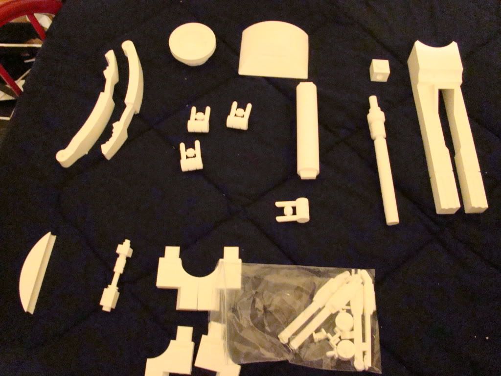
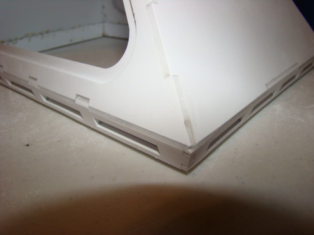
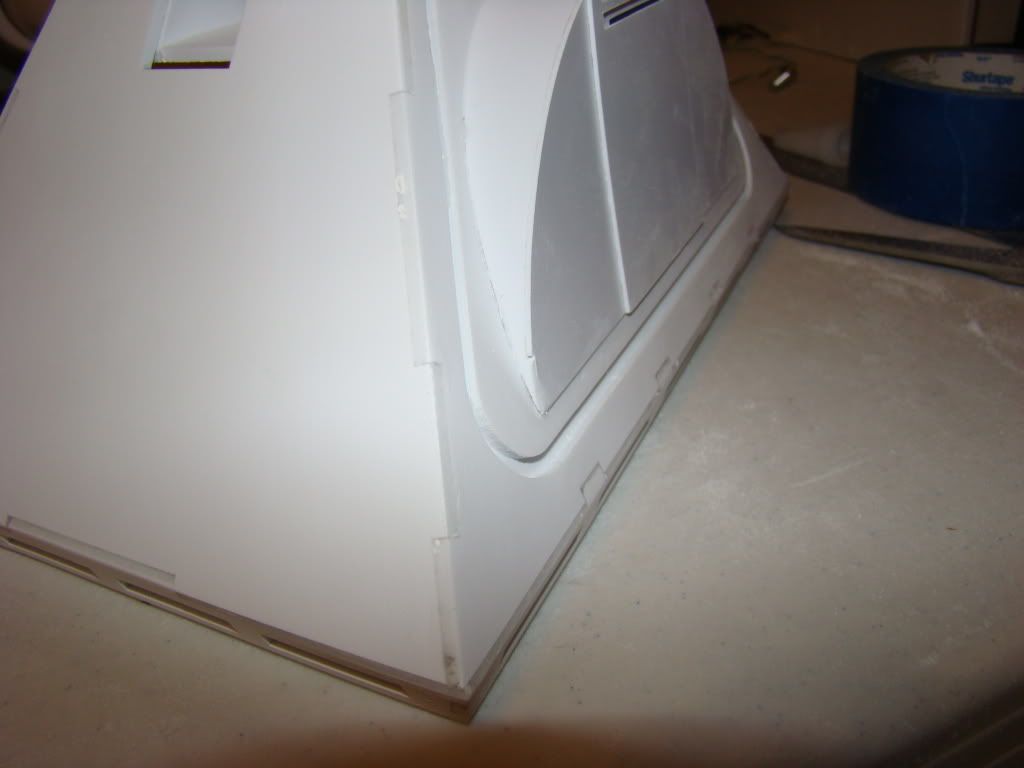
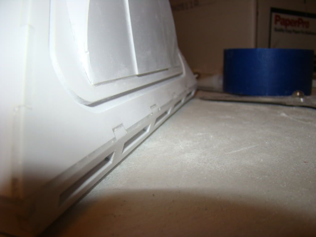
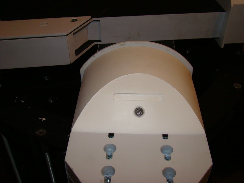
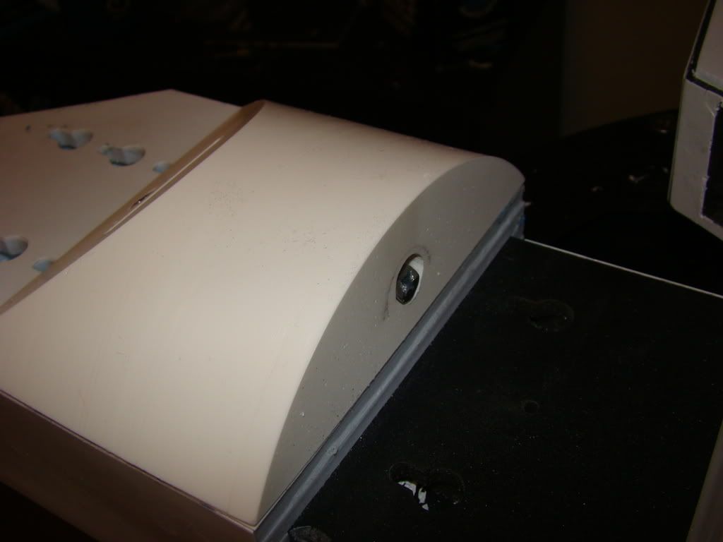
Here's a couple of pics of the "Beefy Ankles" from Resin Parts.com and how they attach.

I just did what I saw Kelly Krider did.


The screws are both drilled by hand at an angle, and countersunk. The ones on top of the ankle didn't work out 100%, so I just took the dremel to the edge that was sticking up.


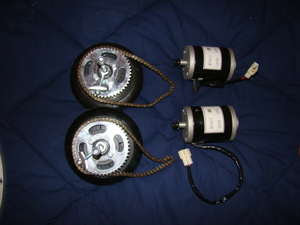
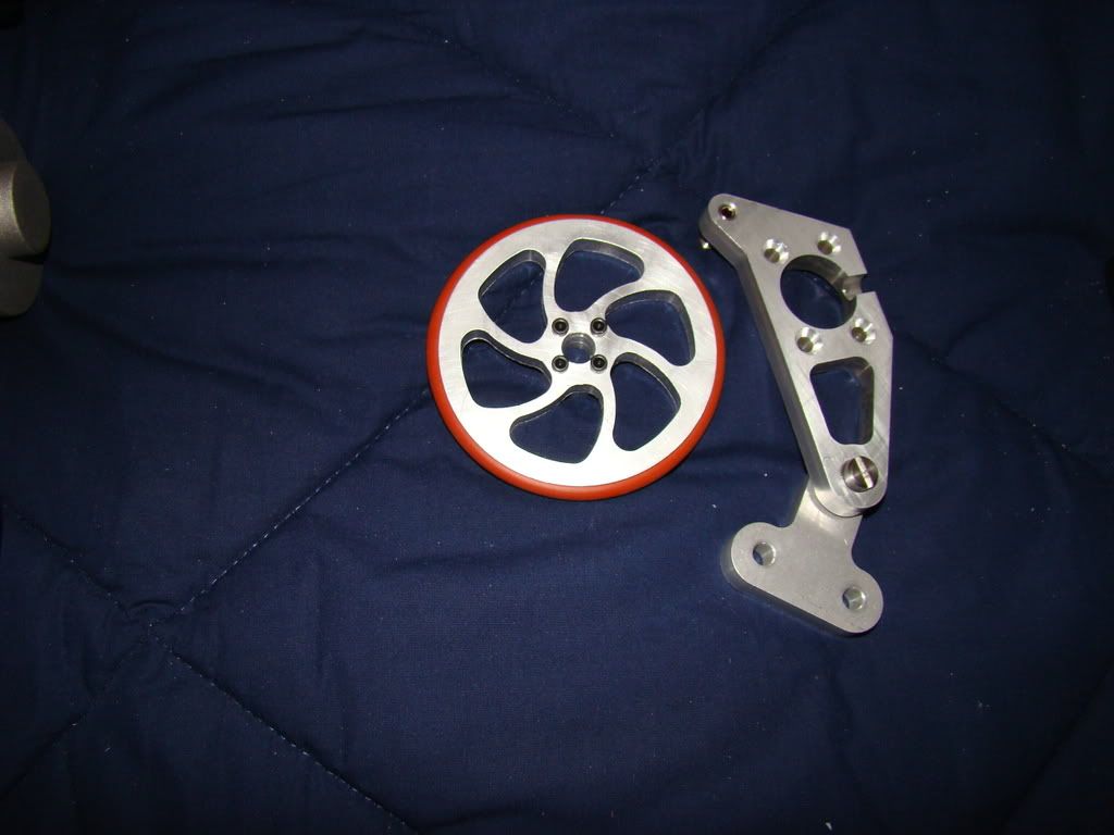
Here's pics of the parts that have come in so far:

Razor E100 wheels, chains and motors.


The dome motor mount assembly and wheel from Atomic Pickle


This week I'll be getting in the speed controllers for both the foot motors and the dome motor, as well as the dome motor and the power dist board from PowerWerx.

I've almost figured out making the motor holders, just got to get the material and the template. Gonna follow the Dan Baker Method for that.

Thursday, December 11, 2008

RC explanation (sort of)

Ok, as promised, going to try to explain the whole RC thing. At least the dome motor and drive motors part.

As a note before I start, the hardware I'll describe is pretty close to what I plan on using. Other stuff might be different...

We'll start with the transmitter. Mine's going to be the Futaba 6EX. That seems to be the most popular one.

The drive motors will be controlled by the left joystick, using what's called "mixed mode". I don't know exactly how it works, but Droidwelder gives a description here. The means that both motors will be controlled by one joystick, using channels 1 and 2.

The right joystick will be for spinning the dome one way or the other using the side to side (probably channel 4).

So, when you use the joystick on the transmitter, it sends the signal to the receiver, which will look a lot like this:

Receiver

When people refer to "channel 1" or "channel 3", those correlate directly to the numbered plug holes on the receiver. So far, our signal has gone from the joystick, out the antenna, to the receiver and to the 3 wire plug hole you see above. They are also sometimes keyed, so you can't plug them in backwards, which would make the motor run backwards.

Next up is the speed controller. A speed controller is exactly like a dimmer switch for a light bulb. News to me, instead of limiting the power like I thought it would have, it switches the power on and off really fast. How fast depends on the position of the switch (in this case the signal). So apparently a dimmer switch turns the light on and off so fast that the filament doesn't have time to warm up completely. Supposedly from an electronics standpoint this is far more desirable, because it produces less heat and stuff. I'll take "their" word for it... It also produces that hum you might hear from a dimmed light sometimes.

The Scorpion XL speed controller looks like this:
Scorpion XL speed controller

Looking at this picture is where everything kinda clicked for me...You can see the 3 sets of 3 wires with the little plugs. Those go to the receiver. Offhand I'd have to guess that the one labeled "right" goes to the channel 1 output, the one labeled "left" goes to the channel 2 output.

And now for a quick break to explain what I think the one labeled "comm" does. On the bottom left side of the board, you'll see something labeled "BEC". This is the connection for the "Battery Elimination Circuit". What this does is provide 5v of power, so that you don't need a power source for your receiver. My only slightly more than un-informed guess is that the set of wires labeled "COMM" will plug into the port for output 8, which is labeled in red in the first picture, thus eliminating the need for a battery for the receiver.

By now things are probably starting to click. The motors will attach to the appropriate screw-down block. The power from your battery (Or power distribution board/fuse block) will attach to the top set of screw-downs. BTW "screw-downs" probably isn't the correct terminology for those parts, it's just what comes to mind without having to research what it really is.

The dome motor will work almost exactly the same, but it will have it's own speed controller, and will use channel 3 or 4, depending on how the transmitter is set up.
I was also told that under no circumstances should you use the BEC from both power boards. One will suffice.

Ok, so that's what I know about RC so far. You'll notice there's an awful lot of "I think" and "probably" going on in there...if I'm not right about something, please don't hesitate to speak up. Better to have to edit a post than replace a part that blew up because I connected it wrong. But that should be enough to clear up a little bit of the mud.

It sure does sound a lot like red wire black wire, doesn't it? Plug it into the right place and it goes...plug it in wrong and it either doesn't go, or it goes backwards :P

Oh, before I forget, a big thank you to Droidwelder over at astromech.net for answering questions for probably the umpteen thousandth time...
Monday, December 8, 2008

Got my shipment in from Resin Parts.com!

Can't believe how cool they are...and how much more work I now have to do...

Here's pics:

Spread out on the bed (not all of them, just the ones that aren't in the next pictures):


Leg parts laid out, as close to in place as I could get them just eyeballing:


Yup, as I said, way more work now to do. And I am digging the "beefy ankles"...they are very cool. I made sure to read the
Working with resin page and I dont' have anything to clean the mold release off the parts with yet, so I'm just letting them sit.

Mainly doing more research this evening...I think I've just about got the RC bit figured out. Once I'm sure I know what I'm talking about I'll tell you what I figured out. :)

Tuesday, December 2, 2008

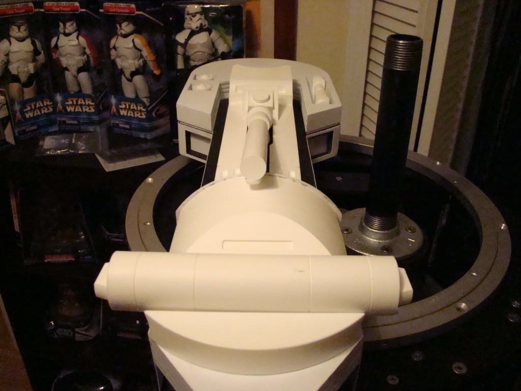
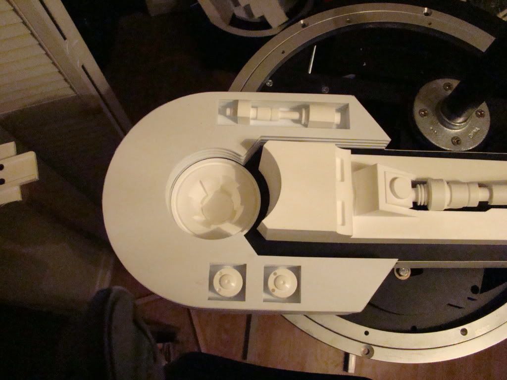
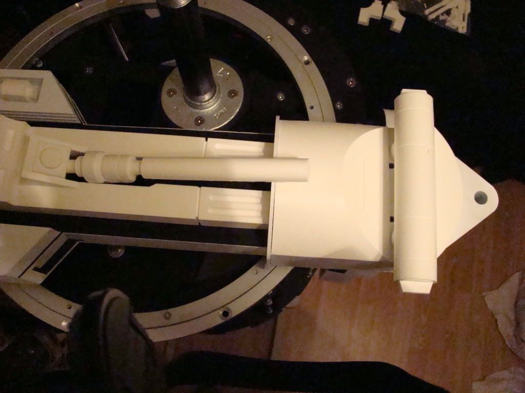
Ok, so you can't really tell in these pics that all the gaps are filled, but here they are anyway...


Monday, December 1, 2008

Oh, as a side note to the previous post, I think I figured something out about the "LPJT".

I'm having trouble getting a single pipe that will fit between the 2 galvanized floor flanges.

Apparently when you thread a pipe, the threads are tapered. Not so much that you'd notice, unless you were trying to thread a flange that quite also might possibly have tapered threads as well onto it.

Basically, my measurement was 14 1/16" between the flanges. I had the very stressed little man at Lowe's leave 14" between the threads when he made the pipe for me. Since I can't thread the flange all the way to the end of the pipe, that just plain doesn't work.

I plan on going to Ace Hardware (Since it's usually old dudes who like a challenge and seeing if they can fix it. My money says yes, although I might have to buy a 3/4" tap and die that I'd never use again....

Anyway, that was important enough to mention since I spent 7 hours Friday working on it. Maybe THIS is why 2 pipes is the common method...

Update

Ok, no pics this time.

Now that I know someone's reading this,

Big shout out to Greedo who makes the best clone carbine you can get your hands on (if you're lucky) :)

The legs are done being skinned with sintra, but there was a mishap...one of the legs fell and the "ankle bracelet" broke. Will have to stupid glue that back on.

Also noticed a slightly bigger problem, but not one that normal folks will see. My horseshoes are identical. Meaning when sitting side by side they look the same and are not mirror images. Means I'll have buttons front on one side, and hydro front on the other. John Q will never notice, and possibly only people who read this will know to look :)

Anyway, got that big box o' parts ordered from Keith at resinparts.com (link in the previous post) and had an email today that it shipped! That kind of motivated me to find something to do.

2 weeks ago I ordered an 8oz bottle of CA glue from the local HobbyTown USA. When I picked it up Black Friday, you'd have thought I was a celebrity or something, because everyone working there wanted to see who ordered it and what I was working on to need that much glue.

Basically, I refuse to use Bondo ever again, and am using CA glue and accelerant as a filler, and then sanding that down. It's working really well so far, except that I didn't anticipate the mess I made sanding, and I'm fairly sure my computers are all now white inside.

Anyway, took about 3 hours (I guess) to do the middle foot tonight. It still needs about 2 minutes of sanding on the top of the foot, just plain didn't get to it tonight, because HEROES, the best show ever, was on. Had to stop sanding so I could watch :D

Also had to buy new accelerant, since the last 2 bottles were empty, and this kind isn't as fast as the last 2, although it could be the cold weather making it take a little longer to "kick".

Well, as soon as I feel I need pics, I'll post 'em.

Thanks for reading :)